Progress on the Marina has been slow, but things are still happening in the background when funds and motivation allow.
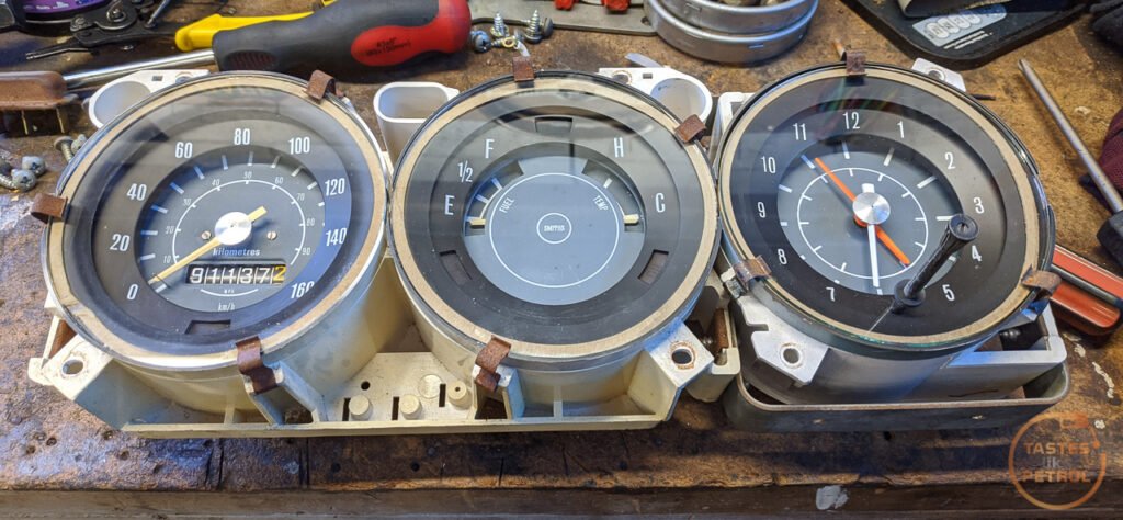
One such thing to happen was the purchase of a three-dial cluster during a recent trip to Horopito Motors (Smash Palace). They had a few clusters there in various states of physical distress, so I picked the best one they had. Unfortunately, it’s from a Super so has a clock and not a tacho as I want, but since the housing is the same between them, all I need to do to fit a tacho is find the tacho unit and swap it out. The main thing is that all the mounting points are intact, and there are no cracks in the housing.

I couldn’t help a quick test fit to see how it looks. Much more upmarket than the two dial cluster.

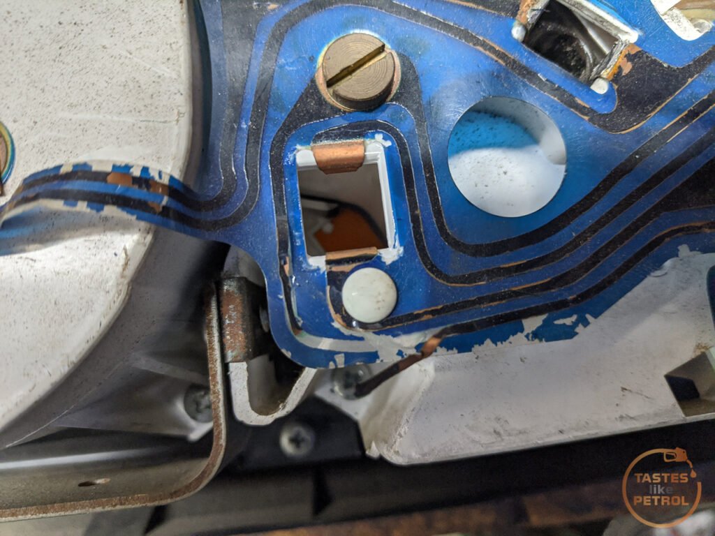
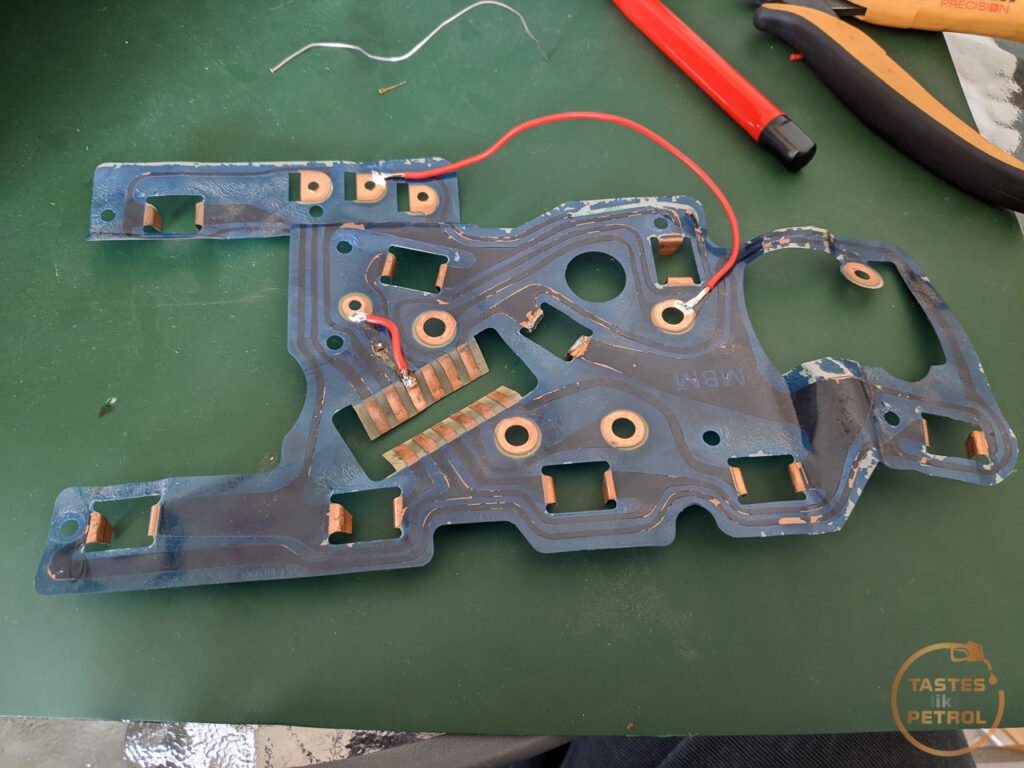
Now, being so dark in the rooms of Horopito, I didn’t notice some damage to the cluster which needs fixing. The flexible PCB on the back has been torn and damaged the copper trace in the bottom corner
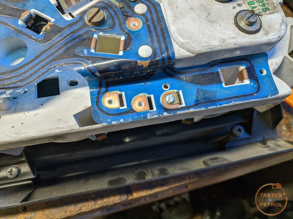
And someone had previously repaired another damaged section of copper trace by wrapping it around some bare strands of wire

It’s not the end of the world though. I do have a good soldering station and I’m not bad at soldering. You just need to be damn careful not to melt the PCB and cause more damage.
Interestingly, here is what I mean about being able to swap the tacho in. On the left in this photo is the clock module. it’s attached to the other two dials by two screws, meaning it can be removed separately.

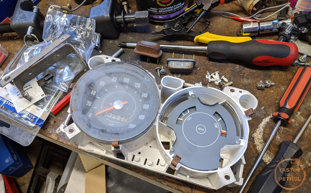
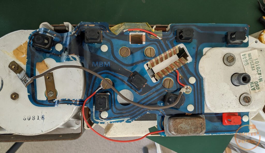
I needed to strip the whole thing down as I wanted to remove the PCB to fix it, and also swap in my two dial cluster in place of this one as the speedo is for a 6 cylinder car and has a different ratio (not to mention the mileage is wrong, and the scale goes up to a crazy 200kph and doesn’t have the MPH sub-scale). This allows me to keep my mileage correct.
The first job is to remove the voltage stabiliser, along with its spade terminals. The stabiliser gently pries off the board, and the terminals are held in with a screw each and you can press them out from the front of the housing with your fingers
Remove all the bulb holders, and the other various screws (including the four big brass ones) and start removing the little white push pins. I found it easiest to gently slide a flat blade screwdriver under the PCB (between the PCB and white housing) and under the head of the pin and then wiggle it. Take care not to poke or tear the PCB. Something like a butter knife might work well for this.

With all the pins removed the PCB should just lift off the housing. Next, I removed the four screws holding the housing to the fascia

and then five screws remove the fascia from the main frame of the surround

Everything got a thorough clean as it was all filthy. The fascia woodgrain appears to be some sort of very thin veneer, maybe even a sticker. It had torn slightly in one corner and it’s clearly faded. Still very useable though. To clean the fascia I removed all the silver rings. These are held on with a twist lock. Just take care when pushing the tabs through the holes not to catch the veneer and tear it.


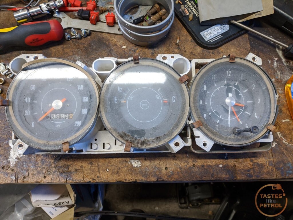
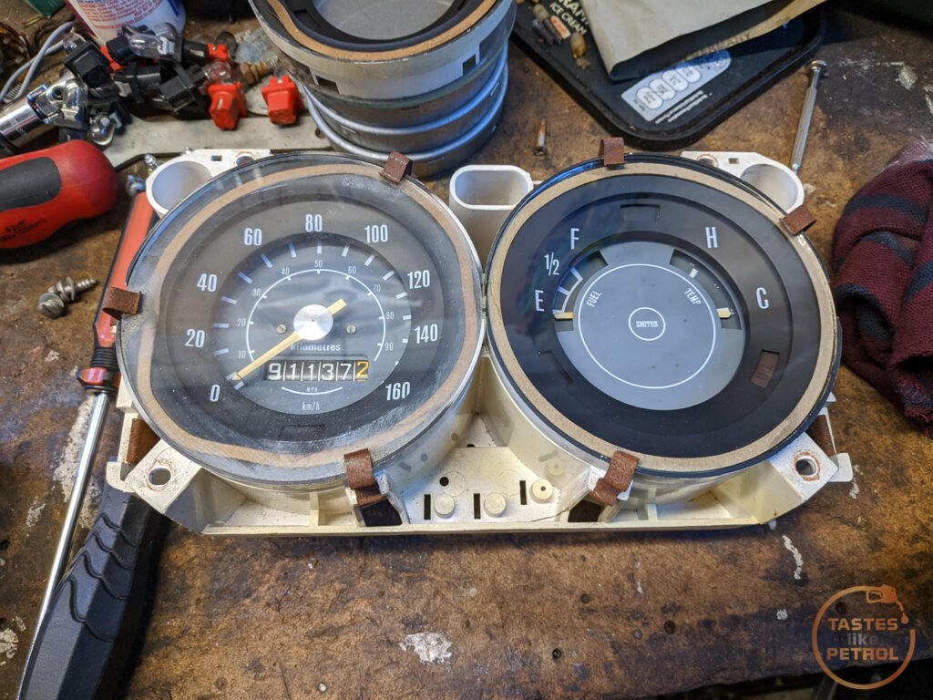
Now it was time to move onto the main dials. You can see the two main dials are just the standard unit from the two dial cluster and cannot be separated.
Two screws remove the clock
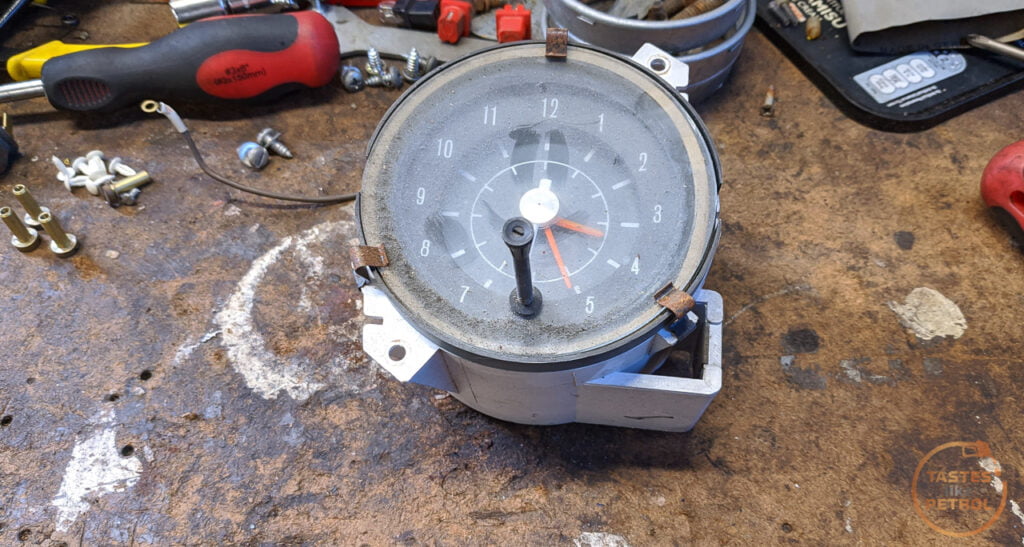
It was so filthy I couldn’t leave it. I tried cleaning just the outside of the glass but found the inside was dirty too, so removed the glass. It is held on with three spring tabs. You can either remove the tabs as they are a press-fit onto the white housing, or just pull back the two on the left with one hand and then lift the glass out with the other. Take care not to touch the black surface inside the gauge as they will fingerprint badly. Don’t damage the paper seal behind the glass either. The adjuster for the time has a tiny little slot screw at the end of it, and when you undo that the knob will come free (note for reassembly, the knob is keyed with a flat on one side)
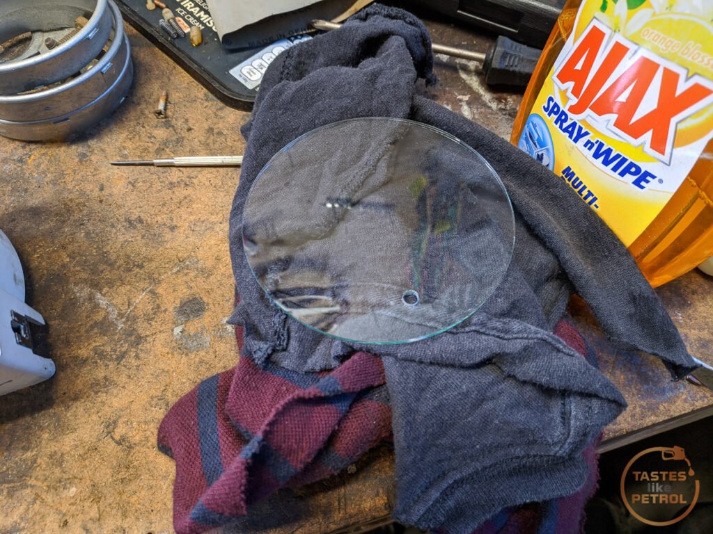

After a thorough clean

I was about to store the donor dials away when I decided to swap the paper gaskets between those and my good dials as they had better seals and the warped seals could be seen when the dials were installed in the fascia. This spiralled into swapping a few other things.
After removing the dirty glass from the donor unit I noticed something. The donor says ALT and OIL on the warning lights, something mine doesn’t have!

I love unmarked warning lights as much as the next person, but I was feeling fancy, so had to find out if I could swap the lenses over.

As it turns out, it’s easy to do. The lenses are attached to that black ring, which is only held on with the spring clips.

Swapped, with cleaned glass and donor seal
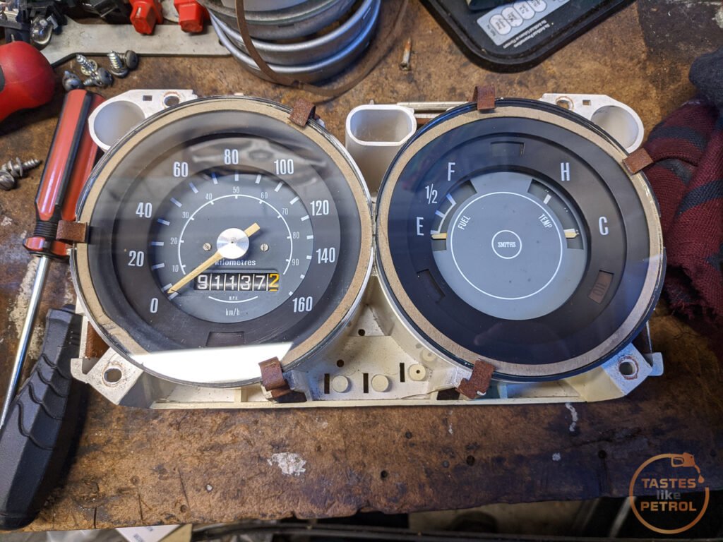
Obviously I couldn’t leave the speedo looking like that, so I removed and cleaned the glass and swapped a better gasket onto it
Now I could attach the clock to my refurbished two dial cluster
I cleaned and refitted the rings. They’re slightly tarnished but still useable.

Now I had to fix the PCB. The best fix I could do was to bypass the damaged traces with a wire, soldered to the nearest big copper pad. First I cleaned the area I was going to solder on the PCB with a fibreglass brush to get any tarnishing or coating off the copper, and then tinned the PCB and end of the wire (yes, I stripped the wire way too far back. It’ll be OK. The others are shorter).

And then soldered the wire to the tinned copper pad. I tried to have the wire as close to the edge and as flat as possible so that it wouldn’t interfere with the screw that goes through the PCB.

That wire is quite long and I wanted to make sure it’d clear the housing. Since its installed back on the housing now I’ll secure the wire with tape. You can just see the other repair below it. I snipped the previous “repair” and soldered directly to the pad and to the top of the plug contact.
I reassembled it, and tested.

It was all going so well until I tried to install an LED into the high beam indicator (as it’s SUPER dim with a bulb in it) and when removing the LED to turn it around and change the polarity to see if it would work, the metal housing of the LED shorted on the back of the PCB and blew one of the traces to bits. Cue much swearing, and soldering a new link in to bridge the burnt-out trace. I had to insulate under this one as its really close to the other traces and I didn’t want them to short out against the new wire.
Another test shows that thankfully I didn’t cock it up completely, and everything works again. Phew.

Well, by “everything” I mean everything but the clock, since that is dead as a doornail. I tried feeding 12V straight into it and it will tick once, the second hand will move, and then it’s dead until I remove and replace power, where it will tick once, again. Very disappointed. So now I’m left with a couple of options. Find a tacho module to swap in. Disassemble and break the clock more fix the clock. Or Find an aftermarket tacho that matches the size and style and 3D print a bracket to hold it in place. Not sure what I’ll do yet, but I do have a lead on a stock tacho, so we’ll see.
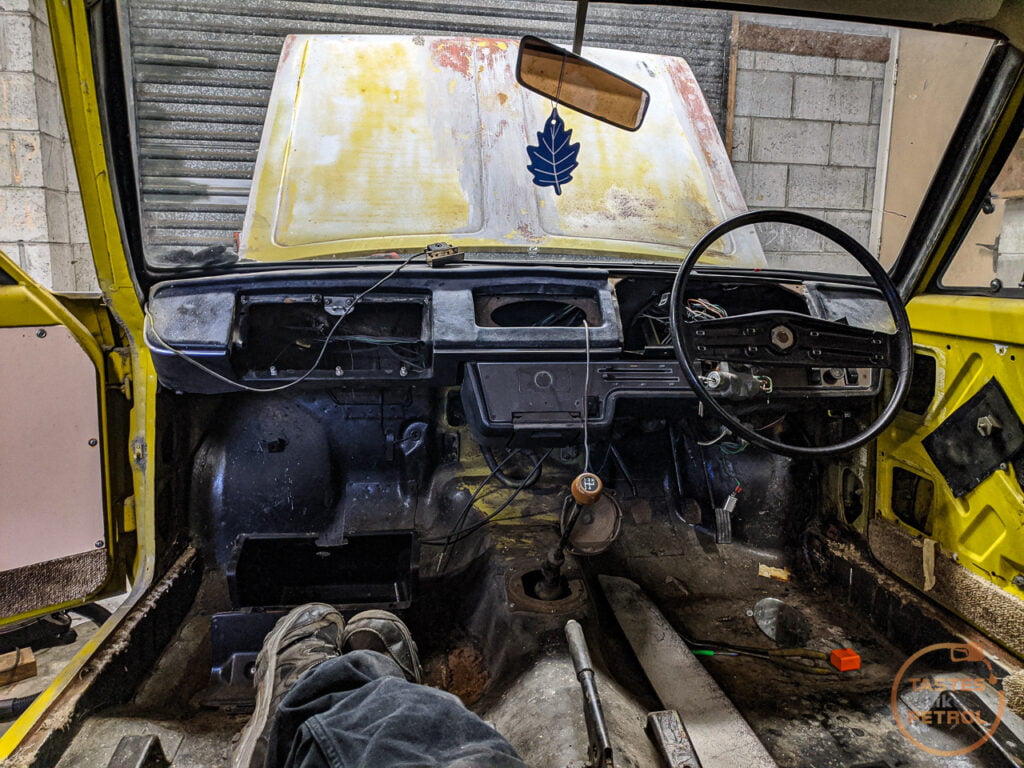
Before giving up for the day I thought I would try some 303 Aerospace Protectant on the super dry vinyl dash. It came up surprisingly well. It’s still very dry and has a lot of overspray on it, but its black, not grey now. It just drank the 303 up, so will keep applying more and see if it softens it over time.
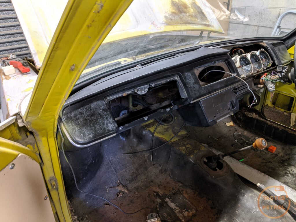
A bit different from how it looked before.
I’ve got a wee box of bits waiting to go into the car, but I’m still waiting on a few more parts to arrive from the UK. I need the BMW to sell before I can really get cracking. It’s listed for sale now, so hopefully someone falls in love with it soon.