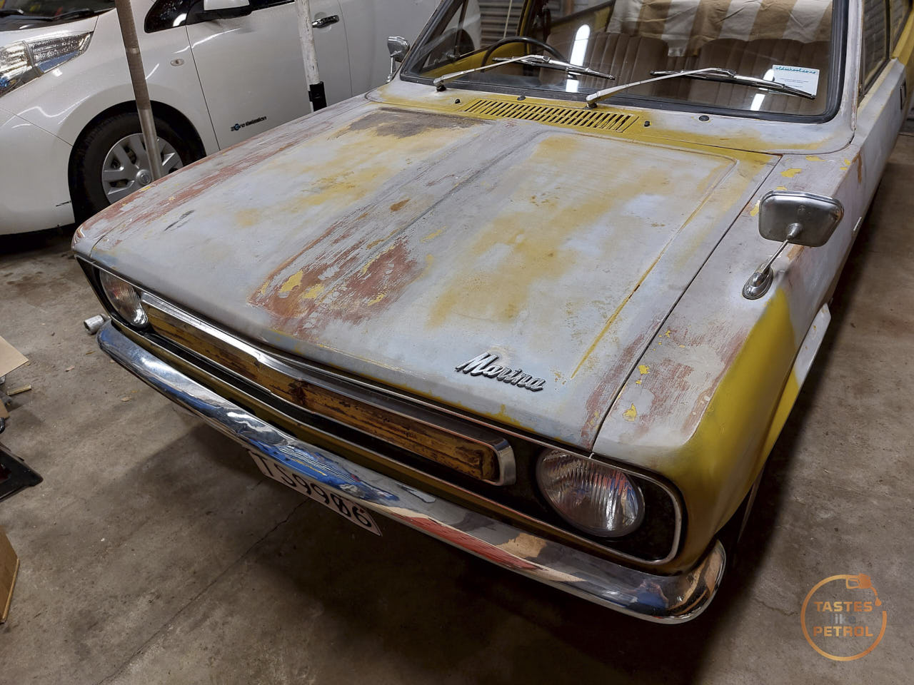
Along with the underside tidy-up that I did in the last update, there were a few mechanical bits I needed to deal with before the next inspection in a couple of weeks.
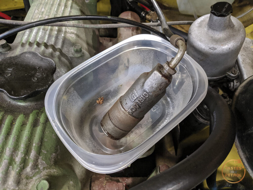
The first one was an annoying one; the leaking clutch slave cylinder.
I knew the cylinder was slowly weeping fluid, and it appeared to be from the bleed valve. I wasn’t too worried as it seemed to lose fluid quite slowly, and I planned to deal with it later.
Unfortunately, on top of all the other things the WOF guy blasted me on, one of them was the damn slave cylinder taking a dump. It was still working fine (despite him using it as a reason for grinding it into reverse, nah mate), but it was actively leaking fluid out the front of the cylinder and down the bellhousing now. Balls.
I was particularly annoyed by this, not just because it was one more thing the WOF guy didn’t like, but because I had already rebuilt it. I sent it out to be resleeved in stainless and I fitted a seal kit I got from the UK.

This time I didn’t bother to strip it, I decided I would have the pros strip and rekit it for me, just in case there were other issues at play.
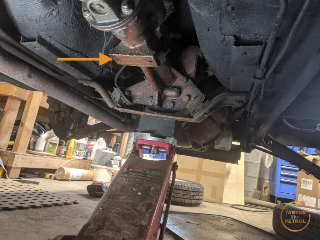
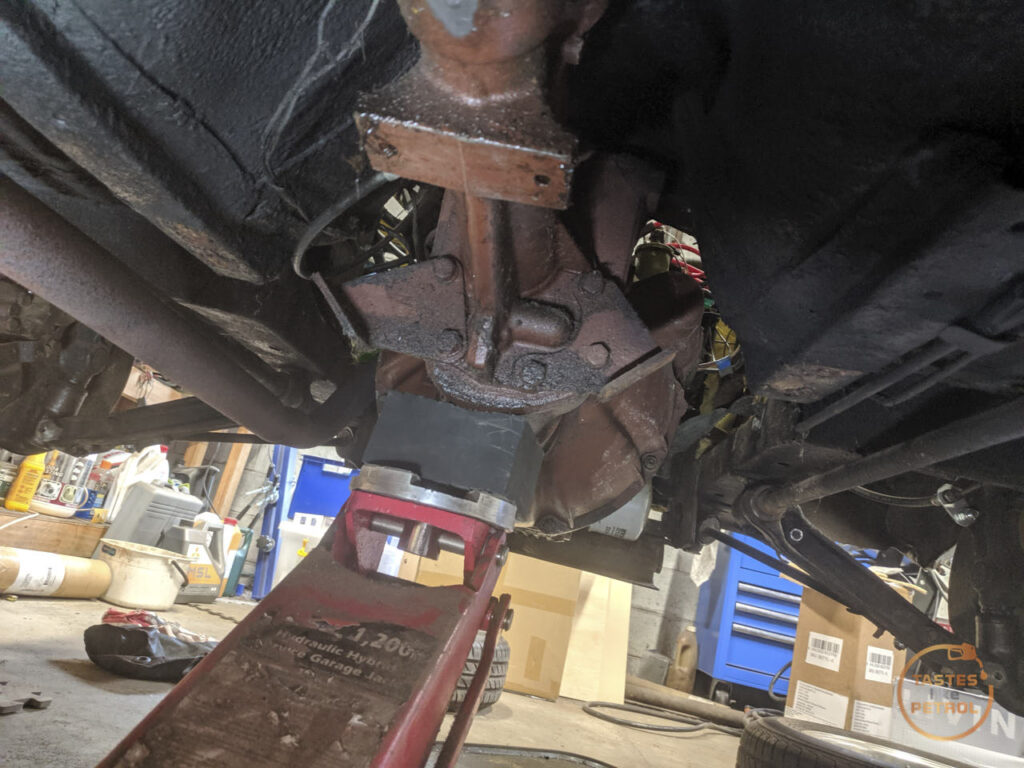
The culprit lurks down here. In hindsight I should’ve painted it after it was sleeved (came back freshly sandblasted)

It’d used half the reservoir of fluid just in the test driving before the WOF, and the drive to and from the workshop

I removed the pushrod, boot and retaining circlip. The boot was full of fluid


With the circlip removed the cylinder just slides backwards out of its retaining ring on the bellhousing, making it a lot easier to disconnect the pipe
A big adjustable spanner is used to hold it whilst the pipe is undone

I was recommended these pipe-end blocking clamp things by a friend, and I’ll be darned if they aren’t pretty handy. Normally I’d just tie a rubber glove finger over the end and deal with a glove finger full of brake fluid later, but this sealed it completely with no mess

The inside of the cylinder wasn’t looking too hot (and the piston was stuck at the bottom…)

And some very fine marking on the bore

I sent it off to the guys that sleeved it originally, CBC Brakes down in Christchurch, and this is what they came back with


The seal had rolled in the bore. I honestly don’t know how that happened, or when it happened. I had no issues fitting the piston, it didn’t catch, and for it to have even been working as it was is a miracle.
Either way, despite my embarrassment at having cocked it up and with only myself to blame, I had them rekit the cylinder with a new seal.
I will say, CBC have been awesome every time I have dealt with them. Their turnaround is super quick, they are reasonably priced and the work they do is faultless. Now I’ve had them resleeve and kit the brake master, clutch master and clutch slave. I’m glad I had them do the brake master, I wouldn’t want to find out I rolled a seal in that! No room for failure with a single-circuit brake system.
The slave cylinder arrived back in record time, and I think they took pity on me because this time it came freshly painted and looking a million bucks.

I quickly set about refitting the slave. I greased the end of the pushrod and refitted it into the boot

The pipe was refitted, and the slave was slipped down into its retainer and the circlip refitted. A few pumps of the hand vacuum bleeder got fluid flowing, and I finished it off with the trusty one-man bleeder bottle.

As an aside, when refitting, despite how much of a pain it is to have the feed pipe on the bottom and blocking the bleeder, the bleeder must be fitted at the top or you’ll never bleed the air out.
In my testing since refitting, the clutch feels much the same, which I guess is good. No leaks though, so I’ll take that as a win and having it properly rebuilt now, hopefully I’ll never have to look at it again.
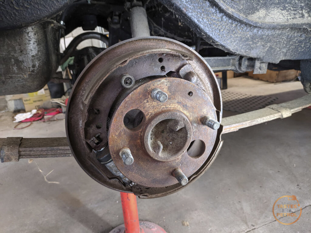
Now, two big things were picked up on in the “WOF” check. The RH rear wheel bearing was grinding, and there was play in the steering.
I started with the wheel bearing. When spinning the wheel there was a definite whirr noise, which wasn’t present on the LH side. I watched a couple of videos on Youtube, and ordered a new bearing kit.
Do note that as my car is an Aus Marina it uses a Borg Warner rear axle, so the work I’ve done may not apply to UK cars, but I imagine the theory is similar.
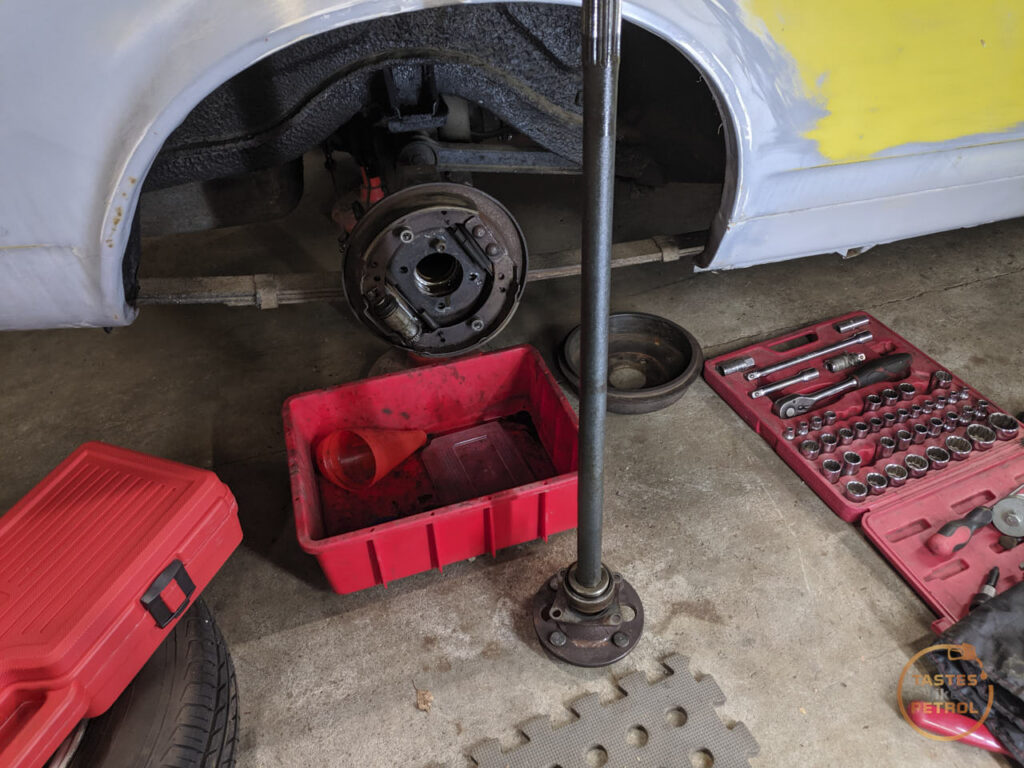
The drum has to be removed first, which exposes the axle
Four nuts secure the retaining plate

These are accessed via the big cut-outs in the face of the hub flange


With those four nuts removed, the axle should pull free from the diff. Should.
Most people say to flip the drum over and secure it with a couple of wheel nuts wound on a couple of threads, and use it like a slide hammer to thump the axle free


This did not work, despite many many attempts. It got to a point where either I was going to pull the car off the axle stands, or break the drum, neither of which I wanted to do.
I got pretty annoyed at this point, and after all my efforts I had only moved the bearing maybe 1mm as I could just see a lip of rusty bearing showing.
A new plan was needed, so I bit the bullet and ordered a slider hammer kit that included the required fittings for axle removal.
In the meantime, I took a look at the play in the steering.
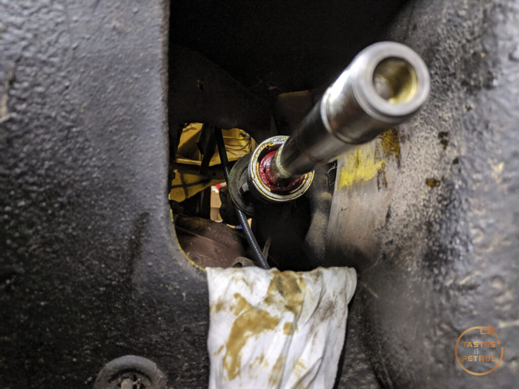
The Marina has a fairly well-known issue where the inner rack support bush on the LH side wears out, as it’s made of nylon, and this allows for play in the inner rack. Because the rack can physically move up and down, this allows for play in the LH wheel.
I checked for play when I first got the car, and I don’t remember there being any, but I ordered a new bush anyway and put it into my spares. Now though, it’s good I did, because when you wiggle the wheel side to side, heaps of movement.
It is recommended to remove the rack, strip it down completely and then bash the old bush out from the other end. There are a few that have done it on the car though, and as I’m low on time and can’t be bothered removing the rack, I chose to do it on the car.
Before doing anything else, crack the tie rod end lock nut, as you’ll need to remove the tie rod end and this can be properly stuck. With that free, remove the nut on the tie rod end and pop the taper using a couple of whacks of a hammer on the arm.

Counting the turns, wind the tie rod end off

Remove the lock nut, and after loosening both clamps, remove the boot. Be aware it should be quite oily.

Interestingly the inner tie rod is actually serviceable and adjustable using a cup and spring setup

The rack end is locked in place with #10 “locknut”, which uses a stake on each end to lock both the tie rod and the rack end together so it can’t come loose. I used my big grips on #8 “ball housing” wiggling it back and forth until the stake on the rack end loosened up, and then I could wind both the housing and locknut off. In the end of the tie rod is the cup and spring. Once on the ground I could separate the locknut from the housing.

With the tie rod out of the way, you can see the worn-out bush. Theres nothing touching the rack

The new bush is made by Nolathane in polyurethane and is part number 41044.

I slid this over the end of the rack, and carefully drifted it into place against the old bushing. Before fitting I measured how deep in the rack the original bush was, and how long the new bush was, so I knew it was fully seated.
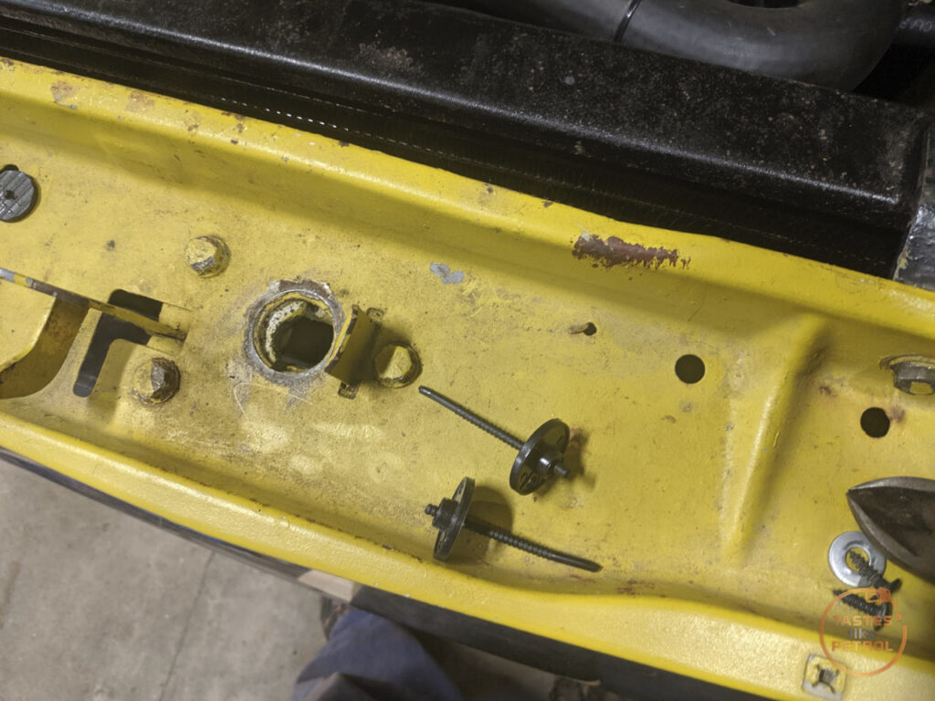
The one catch is that if you aren’t removing the stock bush, you need a new screw in the housing to retain the new bush. To do this you need to drill into the housing and screw in a self-tapping screw. I did this in the bottom of the housing as it was easiest for me to access, but in hindsight, I would fit it higher as I have had to use sealant to stop any oil leaking passed the screw.
I couldn’t find it at the time and only later noticed it in the photo, but the screw retaining the original bushing is there, with the orange arrow. The new screw I fitted is the green arrow. Looking at where the original screw is, I don’t think you could access it on the car.

If the bush comes loose, the worst that’ll happen is that it’ll stop supporting the rack and it’ll be no worse than it was before, since the old bush is still there. If that happens I will remove the rack and fit the new bush properly.
The instructions to fit the tie rod are fairly specific. First screw the lock nut onto the rack and bottom out the threads. Before I did this I used some narrow pliers to straighten out the stakes.
Next, you insert the spring and then the cup, followed by the tie rod and its housing. Screw the housing down until the tie rod is nipped up and cant swivel, and back off 1/8 of a turn until the tie rod can articulate fully but still be firm (the spec is 3.63-4.18nm of force to move). Next wind the locking nut into place and lock it with the tie rod, making sure the adjustment is still in spec.
Now, using a punch, lock the nut to the housing, and the nut to the rack, both of them have indents where the locking gets punched into

Now slip the boot back on, do the clamps up, refit the lock nut and tie rod end (turning it the same amount of turns it came off). Refit the tie rod end to the arm, and its job done.

I haven’t driven the car since, but there is no play in the wheel when wiggling it side to side, and it was really obvious before.
It will be interesting to know how the steering feels now. It’s always been a bit vague and wandered a bit, it’d make sense since it had dynamic toe on the LH side.
While waiting for the slide hammer to arrive so I could yeet the axle out of its home, I ordered a couple of transmission mounts, which arrived quickly.
I did a bunch of research around these because original mounts are NLA, and the Aus cars use a completely different mount setup than the UK cars.
On the UK cars they use a cross-member mounted to the body, and a single rubber mount the gearbox rests on. This mount is attached to the very end of the tail housing on the gearbox, Whilst the Aus cars have a pair of mounts much further forward on the gearbox on a pair of plates and brackets
The orange arrow points to where the UK mount would be on the gearbox
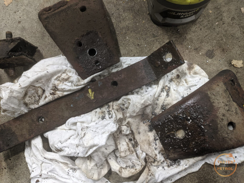
The stock mounts are a weird Z shaped thing, and mine were trashed.

I had an idea I could probably find a cotton reel style mount that would work, and after much digging around the internet I found someone on the Aus Facebook group mention they had successfully used “series Land Rover gearbox mounts”. Some more digging, and I came up with a local supplier of NRC2054
Compared to the original mounts they’re a bit taller, but I have no idea how compressed those old ones are

Getting to that point wasn’t too hard, I supported the gearbox on the jack and removed the bolts for the “cross-member” which is actually two brackets linked by a brace. This allowed the mounts to slide out
The new mounts are metric 10mm studs, so I had to drill out the smaller imperial holes to fit, both on the chassis brackets and on the gearbox brackets (that was fun…).
What came next was like trying to assemble a jigsaw with only a vague picture, and a bunch of bits that don’t fit together. It sucked.

Because the mounts are on an angle, everything has to slot together nicely in a certain pattern, and nothing fit. I ended up having to remove most of the bolts from the brackets on the gearbox, so I could pivot them around, and jack the gearbox up and down

Everything had to remain super loose until eventually it all fell into place, all the bolts went in, and only then could I tighten them all down. Some use of the big lever was needed.

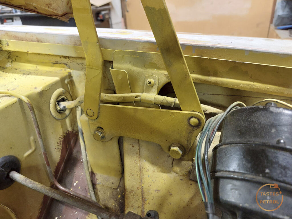
The gearbox definitely sits a little higher now, this was most obvious by the fact that the top radiator house was now firmly trying to occupy the space the radiator fan does. They’ve always had a slightly touchy-feely relationship, but this was beyond acceptable.

I had preempted this, by buying another radiator fan mounting kit. I wanted to move the fan over to give the hose more space anyway (I mounted the fan to the radiator out of the car, before I had fitted the top hose and realised the fan cannot be central on the radiator), so this was my chance.
I snapped all the little ties off, using a metal trim tool on the fan side to gently twist it back and forth until the head popped off

I moved the fan over and gave everything some nice clearance and zipped it into place

Ample space

Technically it’s on the hotter side of the radiator now, so maybe it’ll work more efficiently.
Finally, the slide hammer arrived (to be fair, it arrived after the weekend. This work all happened over the course of a couple of days)

I ain’t playing around now. I tried asking nicely.
I attached the fitting to the hub

And screwed the hammer into it

Three decent thumps, and the axle was out. It’s amazing what you can do with the right tools.

Forget Loctite, rust is the best bearing retainer

I pulled the axle out and cleaned the oil off it
It’s not really any surprise I needed a slide hammer to remove it, the manual does call for special tool 18G A284 “impulse extractor”, which looks suspiciously like a homemade slide hammer.

To say it needed replacement might be an understatement
To actually replace the bearing you either need to press it and its retaining collar off, or just do what everyone does and cut them off.
I stuck the axle in my vice and zip-tied the retaining plate away so I had less chance of cutting that off by accident

I fired up the death wheel and got cutting. The retaining ring was first to go

Once it was cut most of the way through I stuck a chisel in the cut and a couple of hits split the metal and it slid right off
The same happened to the bearing. I cut through the outer race in two places and broke it away

I removed the balls and inner cage and then cut into the inner race. Once again, when I was mostly through it I smacked it off with a chisel

You can see here I only needed to cut so much of it before the chisel just forcefully cracked the rest of the way. It only took a couple of hits to split. Also note the dull grey area to the left of the cut, this is the reason you must wear PPE doing this, as that’s where a chip of steel must’ve broken off and flown off at high velocity. You don’t want that in your eye.

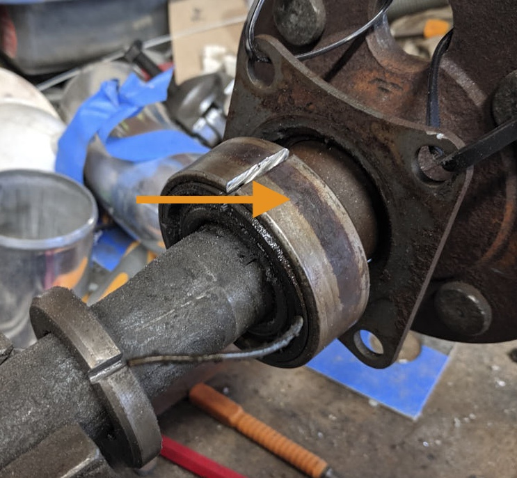
Strangely the races of the bearing seemed pretty ok considering. This was the worst damage I could find; a couple of marks on the inner race

It’s interesting to note though that you can see where the bearings run on the outer race, it must’ve gotten hot?
With both bits loose I removed the axle from the vice and shook them free. Now it was time to fit the nice new one

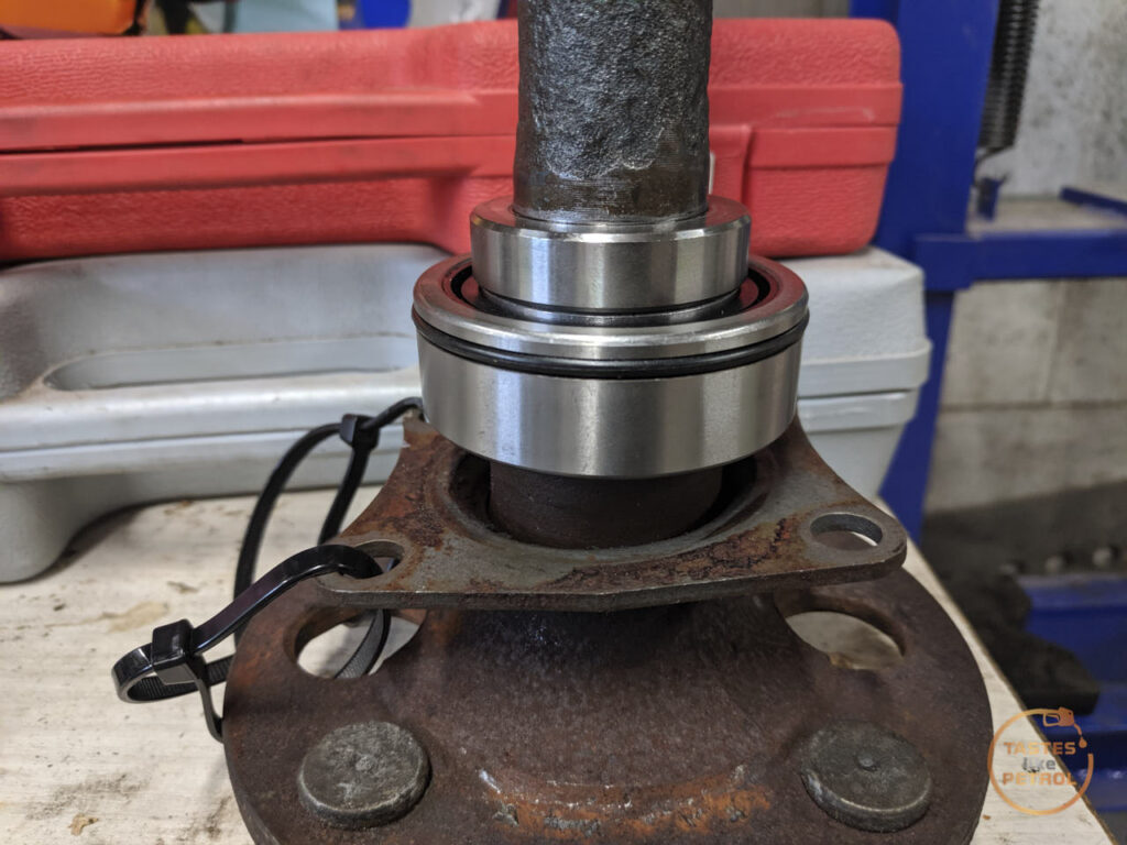
The kit comes with the bearing and a new retaining ring. Do note when fitting these that the bearing has a raised lip on one side (facing up in the above photo), this must face the hub flange when fitted

Making sure the retaining plate was in place, I carefully slid the new bearing onto the axle and mounted the axle into the press. I’m using the old retaining ring to press the bearing on, as it will only exert force on the inner race of the bearing, and having been cut it won’t bind on the axle shaft. My biggest socket gives the press a flat surface to work off (slightly bigger would’ve been nice so it could sit on the ring not just the raised bits in the middle, but it’s not often I’d need bigger than 36mm)

Here’s the old retaining collar being put into use

I slowly pressed the bearing on until it bottomed out

With the bearing in place I slid the old ring off, and the new ring on. The old ring was then used to press the new ring on

And done
The bearing spun smoothly by hand, albeit with some resistance from the grease inside the bearing
I gave the housing a good clean up with a scotch pad to remove any rust that might stop it sealing. It was pretty manky

I don’t know if it’s right or wrong, but I read others have done it, so decided to use a very thin smear of sealant on the surface the outer O-ring seals on. The old bearing was the type that is just a friction fit, but this type relies on that O-ring to keep the diff oil where it needs to be (along with the bearing being sealed).
I carefully slid the axle through the backing plate and into its home. I gave the hub flange a couple of hits with the soft face hammer to make sure it was seated.
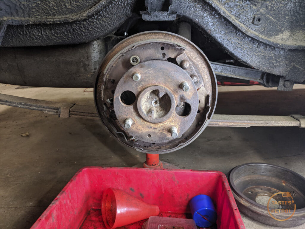
With the four nuts tightened down on the retaining plate, the drum went back on

Finally, the wheels were refitted. Before lowering to the ground I spun the wheel and noticed it had a noticeable rumble when spun. Asking around, it appears this is normal for new sealed bearings due to the grease in them, and even bearing manufacturer SKF suggests running the bearings for a few km (or 10 minutes) for the grease to break in, so I’ll give it some time and check back later and make sure it’s all working as it should.
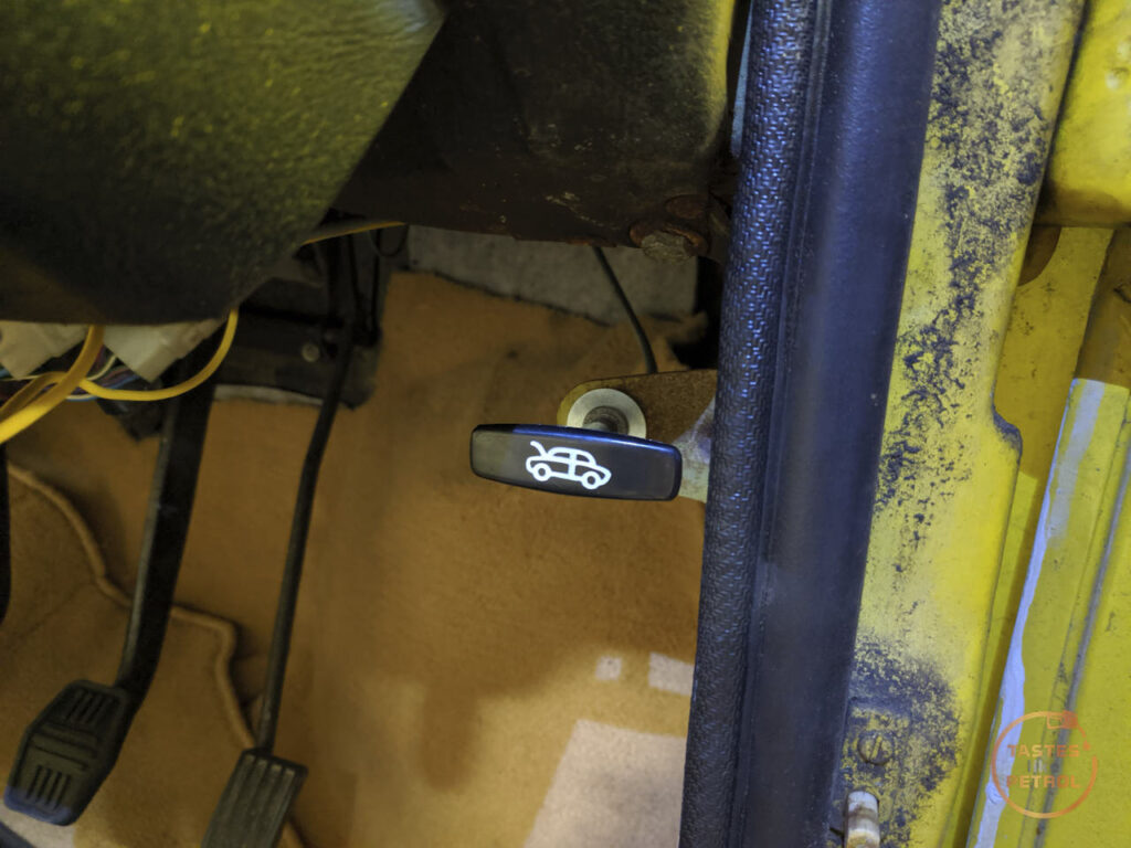
Once on the ground, there was one last job on my list and that was to replace the bonnet cable. The old one was really stiff to pull, and half the T handle was broken off, risking the other half breaking off and being a pain to open.

Doing some googling around it seemed like the MGB bonnet cable was able to be used, so I ordered a CHA460
To remove the old cable I had to remove the front grille, and that gave me access to the cable and bonnet catch. The cable loops through the release lever and is then secured in that little screw thing. The cable outer is secured in a clip on a bracket to the left

I undid the cable and removed the clip, allowing me to remove the cable

I undid the nut holding the handle in place and pulled the cable through the car. Refitting the new cable is just a case of putting the cable through the bracket, securing the handle with the nut, and running the cable through the engine bay to the bonnet catch. The new handle body is a bit smaller than the old one so I used an appropriately sized washer to make it fit better
Unfortunately the CHA460 is too short. The cable inner just makes it and can be secured in place, but the outer has no chance of being clipped in place. From my measurements the outer needs to be about 155cm long and the inner 160cm or so.

The cable works as it is, and works really well, the bonnet is much easier and nicer to open, but I need to secure the outer, maybe with a clip or just a zip-tie to that hole there.
While in the area I finally took some time to adjust the bonnet properly. It’s always sat a bit off, and I’ve had issues with the bonnet popping when driving, which led to some bodges to make it work before the last WOF check.
I undid the bodges and found the adjustment slot in the end of the catch pin was so full of gunk you couldn’t see it at all, so after some digging it out, I could adjust it properly.
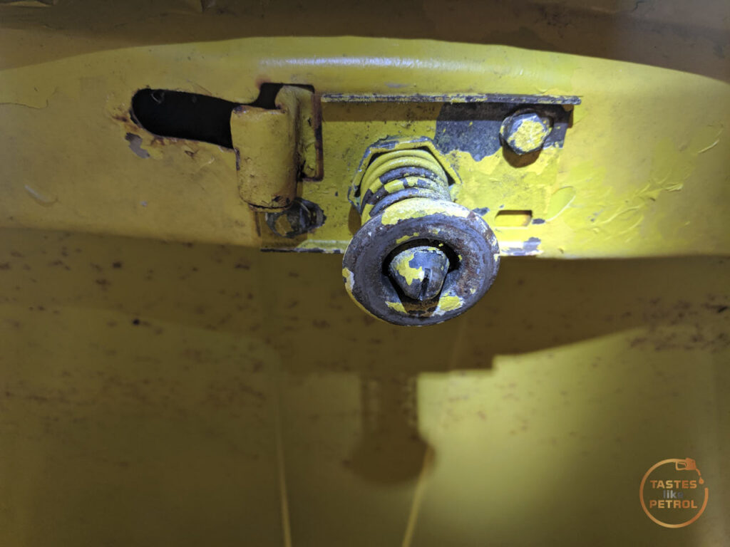
To free the center pin up, I removed the catch and put it in the vice. Using my rattlegun with a slotted screwdriver bit, I gave it a quick jab of the button, which instantly freed the pin up.
I refitted the catch and adjusted the pin to the spec in the book; A= 50.8mm


I had to wind it out significantly to get that measurement, it was at least 10-15mm too short.
I used the slotted adjustment holes in the catch to move the bonnet left or right when closed, and get the gaps nice. After some playing with the hinge adjustments

Along with the little rubber bumpers

I was finally happy with how the bonnet shut. It sits a little high in the middle at the back due to the seal, so I’ll need to look into that, but otherwise it’s good.

That’s pretty much the car buttoned up again and ready to go. I did do a string alignment to check how the toe was, but I’ll do a write up on that later as this post is already getting too long.
I’m two weeks out from my next inspection, which I’ve specifically booked as a “pre-WOF” inspection, or a WOF that won’t be entered into the system if it fails, just in case. Surely I’m running out of things that it can fail on?
Hope it goes well. I thought my Audi was going to pass on WoF day 3, and they decided one tail light was a bit dim. Sigh.