With the rods all balanced and ready to fit, it was time to begin further assembling the engine.
Since I had the engine machine shop fit the crank for me, I checked the torque on the main caps and before fitting the block to the engine stand, fitted the rear main seal (as it’s hard to access after fitting the bracket for the stand).
I started by knocking the old seal out of the retainer and giving it a clean

The new seal then got tapped into place

To protect the seal from catching on the crank during fitting, I cut up an old water bottle and used it as a sleeve to slide the seal onto the crank, not forgetting the new gasket, of course

I then refitted the bolts and a pair of new screws, torquing the bolts to the required 10NM.

Once the excess gasket was trimmed off the bottom, the engine stand bracket was attached

and onto the stand the block went

This allowed me to flip the block around when needed, like fitting the pistons, which was next.
The machine shop also measured, gapped and fitted the rings to the pistons, so all I needed to do was spin the rings around and align them correctly. Its more or less the same thing as the Suzuki manual, but I chose to go with the Greddy instructions to align the rings. What you’re trying to achieve is having no two rings with the gap in the same place, otherwise oil and compression can slip on by the ring.

I carefully spun the rings around to the required places, and then fit my ring compressor

To protect the crank, I used some rubber hose slipped over the studs on the big end

The piston and rod then got carefully lowered into the block, making sure the arrow on the top was pointing towards the front. Once the ring compressor was touching the top of the deck I pressed down on it, so that all the layers of the compressor were touching and there were no gaps (or a ring could pop out before it goes in the block).

Using the plastic handle of my soft face hammer, I slowly tapped the piston down into the block until the compressor popped off. The rubber hoses guide the rod onto the crank, but it helps to guide it by hand too

I did a quick check with Plastigauge to make sure the new rod clearance was fine, which it was

The rod was then carefully pushed back up and lubricated with engine assembly lube, before sliding it back down and fitting the cap, torqued to 35NM

Mmm shiny

The rest of the rods were lubed up, and fitted into the block


With the rotating assembly finally reassembled, and rotating nice and smooth, I could give the oil pump a quick check and fit the new gears I ordered, to replace the damaged ones found in my last post
This is what I started with. I suspect the donor Cappo engine had a leak or two

Using a mix of the ultrasonic cleaner, brake cleaner and a tooth brush, it got a bit better

I pressed the new crank seal in

I had the new gears, and a pressure relief valve kit to go into the housing

The relief valve is held in place with a circlip. There is spring pressure behind it, so take care when removing the clip

Nice shiny new gears


I oiled everything up, and fit the new gears


You can’t really see from the photo, but this is where I suddenly found that unknown to me, there was a supersession to the oil pump in about 1994, which obviously changed the width of the internal gears, as they were thicker than the stock ones and had no chance of fitting. They stick out well proud of the back of the pump.
The old gears were 6.5mm thick, whilst the new ones are 8mm
Old gears on the left.


16130-70B01 does not fit early oil pump housings. Hopefully that stops someone else from making the same mistake.
So that sucks. I have managed to source a new complete oil pump, of the newer updated number, from Japan, and I’m currently waiting on that to ship to NZ. There are some differences with the pump, which I will go into when it arrives, but they have been used on Cappo engines to replace the older pump.
With that disappointment behind me for now, it was time to build the head.
I 3D printed this pretty cool parametric head component holder I found online, after some tweaking to suit my needs


All the valves were pretty clean over all, just some carbon which cleaned up with upper cylinder cleaner and a wire brush


I spun the valves in my drill to help clean them with the wire brush

The head was looking very nice after the machine shop gave it a skim and clean

Speaking of cleaning, I was disappointed to find that like the block, they didnt remove the oil gallery plugs. I flipped the head over at one point and a sizeable chunk of swarf from the skimming dropped out. I removed all the gallery plugs and found a concerning amount of metal in the oil galleries


I hosed all the galleries out with brake cleaner until everything came out clean. There was still a surprising amount of sludge buildup in the feed for the hydraulic lifters too. The plugs all got refitted with some loctite to seal them.
It’s a good reminder that even if you pay someone to clean a component, make sure you go through and give it a good final clean yourself. That metal in the oil galleries could’ve swiftly killed this freshly rebuilt engine.
With the head flushed I set about lapping in the valves. The kit comes with both coarse and fine grinding paste


Basically, the idea is that you put this grinding compound, which is paste with grit in it, on the valve, and use it to grind the valve face into the valve seat, for a better sealing. I had two valves that failed my test before disassembly, so this gives me the chance to fix that.
Grinding paste on the head of the valve. Make sure no grinding paste gets on the stem of the valve, or it’ll be grinding into things you dont want ground. I started with the coarse compound before moving onto the fine.

There are plenty of videos online of how to lap valves by hand, so I won’t go too far into it, but I will say that when you think you’re done, you probably arent. In saying that, you can actually lap valves too far and end up needing them to be reground.
What you’re looking for is a nice uniform band of grey around the valve, like the one on the right (left is untouched). The F6A spec is 1.1-1.3mm width for that band.

I had some trouble with the supplied sticks, since the smallest suction cup only just fit the valves.

The ones in the kit were also straight with no shape, whilst digging around in my roll cab I found some that had more of a shape like this, which was much nicer to use

This is the sort of finish you’re aiming for when lapped in

I thought I was done on this one, but testing showed it leaked. The dark grey spots are all very fine pitting in the seat, which allows it to leak. Thats what we’re trying to remove.

A little more work and the spots were mostly gone, and the valve was sealing

Once all the valves were lapped, I cleaned the head thoroughly to remove any excess grit

To test the valve sealing, I flipped the head back over, installed all the valves without springs or seals, and filled the chambers up with WD40, as this is a very thin oil, so if it was going to leak anything, this should find a way.

I left it for just over 24 hours like that, and it passed with no leakage. Keep in mind last time I tested it before disassembly, with thicker coolant, and springs fitted, I had two valves that leaked.
I cleaned all the WD40 out, removed the valves and cleaned everything again. Now it was time to flip the head over and assemble it
The lower spring seats must go on first, as they do not fit over the stem seals


Next was fitting the stem seals

I’ve seen people improvise tools to fit these, and damage them, but I couldnt afford to damage any (I had a couple of spares just in case anyway), so bought a tool for the job

I used the smallest fitting, oiled it up and slipped the seal in until the shoulder is supported

And gently pressed it into the head. Two clicks and it will be correctly seated


Very quick and easy to do, and perfect results each time

Lots of plastic waste though, since each seal is individually packaged

All seals fitted

Before going any further, I wanted to quickly swap out the exhaust manifold studs with the new ones I purchased. A combo of vice grips and double nuts removed them


Because the holes the studs go into arent blind, and are open to the inside of the head, the new studs come with thread sealant on them. One went in fine, but one of them actually stripped all the sealant off as it went in, so I removed it and used liquid sealant when refitting.

Nice shiny new studs

Back to the valves. The springs were next. As per the manual, each spring has a top and bottom end, with the bottom end against the head having tighter wound coils

I made sure they were the right way around, and dropped the spring into the head, over the valve which had been oiled up and slipped into place


The top retainer was placed on

And then the spring compressor was fitted and wound down, so the collets could be slipped into place

The collets are fiddly little buggers, but I got all of them locked in place eventually


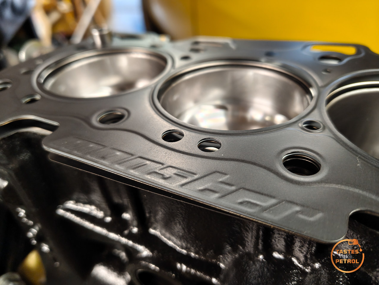
With the head assembled, there was only one thing for it. I cleaned the deck of the block up, tapped the dowels into place and dropped the new Monster Sport head gasket into place, checking all the oil holes line up correctly

The head was then placed on, along with new head bolts. The bolts were torqued up to the required 60NM, in the required pattern (inside to outside, crisscross) and in steps of 20NM (do them all to 20, and then 40 and finally 60NM),

And there we go, finally looking more like an engine again


I couldnt help but try out my refreshed cam boxes


Love the retro look of them, they should look awesome in the engine bay.
Unfortunately until the oil pump arrives I’m at a little bit of a standstill with the engine. I don’t want to assemble the cams until the bottom end is buttoned up, so it’ll have to wait.
There is plenty more going on in the background for the rest of the car, but motivation is lacking, so progress is a bit of a grind at the moment.
Parts Used
Conrod Nuts – 09159-08033 x6
Head Bolts – 11117-52E10 x8
Block Dowels – 04211-13189 x2
Valve Stem Seals – 09289-05012 x12
Valve Collets – 12932-24400 x24
Rear Main Seal – 092836-0009
Rear Main Screws – 02122-0625A x2
Rear Main Housing Gasket – 11349-73010
Exhaust Manifold Studs – 14118-81400 x2
Oil Pump Gears – 16130-70B01 – DO NOT USE ON EARLY PUMP
Oil Pump Cover Screws – 02122-06167 x5
Oil Pressure Relief Valve Kit – 16150-60A20
Please note these parts are specific to my car and may vary. Please check before ordering.